Additive Manufacturing (also referred to as 3D printing) is a manufacturing process that starts from either a raw powder, resin, or filament of a given material, and via layering and slicing, creates a part according to a 3D design. There are many technologies within the Additive Manufacturing Ecosystem, such as FFF (Fused Filament Fabriciation), SLA (Stereolithography), and DMLS (Direct Metal Laser Sintering), to name a few.


Partnering with HARBEC for Additive Manufacturing Services
At HARBEC, we deliver precision components and prototypes, using a variety of manufacturing methods. Our dynamic range of rapid prototype solutions, coupled with capabilities in precision tools and molds and injection molding, enables us to offer a complete solution for customers in one location. HARBEC also provides the following design support:
Part Design Optimization
- Performance
- Appearance
- Manufacturability
Material Specification
- Cost vs. Performance
- Supply Risk Mitigation
- Bioresins
Tool Design
- Tool Life vs. Tool Cost
- Tool Cost vs. Part Cost
From initial design and concept modeling stages, through advanced production tooling requirements, to low or high volume production injection molding and secondary processes, HARBEC takes full responsibility for meeting our customer’s requirements. HARBEC creates value for our customers by reducing manufacturing risk through innovation, superior technical knowledge, and application of state-of-the-art equipment, materials, and know-how. Please fill out this form to receive a quick quote for your product.
Additive Manufacturing Modalities
Build Plastic Parts with Our Selective Laser Sintering
Laser-sintering is well known as the technology of choice for ensuring the quickest route from product idea to market launch. Selective Laser Sintering (SLS) is an additive process where layers of powder are deposited, then solidified with a computer-driven laser to form a 3D model. Selective Laser Sintering produces complex and finely featured parts with exceptional accuracy and unlimited design flexibility. Part stacking and nesting means faster build times, more productivity and less waste, making SLS a practical process for low volume production parts. Because SLS prototypes and parts are not cut from stock, less material and less energy is used.
Get A Handle On Your Ideas… Within A Week!
Going to a show and need to have fully functional parts? Call us. We will work with you to meet your rapid product development schedule. With the capacity of two 3D Systems Sinterstations, we offer more material choices, more flexibility, and more benefits than ever before. From one to one hundred thousand pieces, we will deliver just what you need when you need it.
Transform 3D Data to Dimensional Objects Quickly
Turn 3D data into three dimensional plastic, elastomer, or metal objects utilizing any, or a combination, of our advanced technologies. Parts from HARBEC’s new SLS equipment build up to 11″ x 13″ x 17″ and require no support structures. The variety of SLS materials available and the accuracy of the process allow parts to imitate, or actually be final products. To expedite your design process, HARBEC’s Real-Time Collaboration program enables you to work out details with our design engineers and our expansive library allows us to translate over 50 CAD file types.
Our Rugged Materials Will Withstand Rigorous Testing
With SLS, a wide range of materials such as nylon-like polyamides, glass-filled polyamides, and rubber-like elastomers are available. SLS prototypes are built of rugged materials that will withstand aggressive functional testing under a variety of conditions. This allows designers the ability to refine and verify the part design. SLS parts resist heat and chemicals, are impervious to water, can be painted or dyed, readily joined mechanically or by adhesives and are able to be machined, and welded. The long-term stability of many materials means parts can be used in final applications.
The Simple SLS Process:
- Start with your 3D CAD data.
- Enter the data into the Sinterstation.
- As the process begins, a precision roller mechanism automatically spreads a thin layer of powdered SLS material across the build platform.
- Using data from the generated STL file, a CO2 laser selectively draws a cross-section of the object on the layer of powder. As the laser draws the cross-section, it selectively “sinters” (heats and fuses) the powder creating a solid mass that represents one cross-section of the part.
- The system spreads and sinters layer after layer until the object is complete.
- Remove the part.
Stereolithography is an additive manufacturing process which employs a vat of liquid ultraviolet curable photopolymer “resin” and an ultraviolet laser to build parts’ layers one at a time. For each layer, the laser beam traces a cross-section of the part pattern on the surface of the liquid resin. Exposure to the ultraviolet laser light cures and solidifies the pattern traced on the resin and joins it to the layer below.
After the pattern has been traced, the SLA’s elevator platform descends by a distance equal to the thickness of a single layer, typically 0.05 mm to 0.15 mm (0.002 to 0.006 in). Then, a resin-filled blade sweeps across the cross-section of the part, re-coating it with fresh material. On this new liquid surface, the subsequent layer pattern is traced, joining the previous layer. A complete 3D part is formed by this process. After being built, parts are immersed in a chemical bath in order to be cleaned of excess resin and are subsequently cured in an ultraviolet oven.
Stereolithography requires the use of supporting structures which serve to attach the part to the elevator platform, prevent deflection due to gravity and hold the cross sections in place so that they resist lateral pressure from the re-coater blade. Supports are generated automatically during the preparation of 3D Computer Aided Design models for use on the stereolithography machine, although they may be manipulated manually. Supports must be removed from the finished product manually, unlike in other, less costly, rapid prototyping technologies. Wikipedia
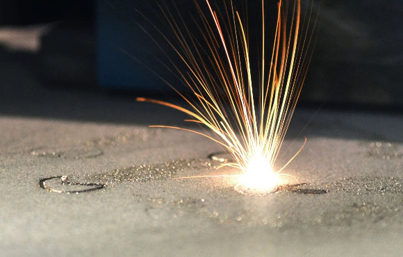
Build Metal Parts with Our Direct Metal Laser Sintering
Take advantage of HARBEC’s EOSINT M 290 and EOSINT M 270 laser sintering systems for the production of tooling inserts, prototype parts and direct manufactured parts in various metals. The Direct Metal Laser Sintering (DMLS) technology fuses metal powder into a solid part by melting it locally using a focused laser beam. Similar to SLS, the parts are built additively: layer by layer. Even highly complex geometries are created directly from 3D CAD data, automatically, in just a few hours without any tooling. It is a net-shape process, producing products with high accuracy and detail resolution, good surface quality and excellent mechanical properties. A wide variety of metals can be direct metal laser sintered, ranging from light alloys via steels to super-alloys and composites. DMLS is widely used to produce positive parts directly from CAD data. The components can be prototypes, series production parts or even spare parts. DMLS is also well known as a leading technology for tool making using an application known as DirectTool. With its high accuracy and surface quality, the direct process eliminates tool-path generation and multiple machining processes such as EDM (Electrical Discharge Machining). Tool inserts are built overnight or even in just a few hours. With DMLS, the freedom of design can be used to optimize tool performance, for example by integrating conformal cooling channels into the tool.